HSID Main (hsid_main)
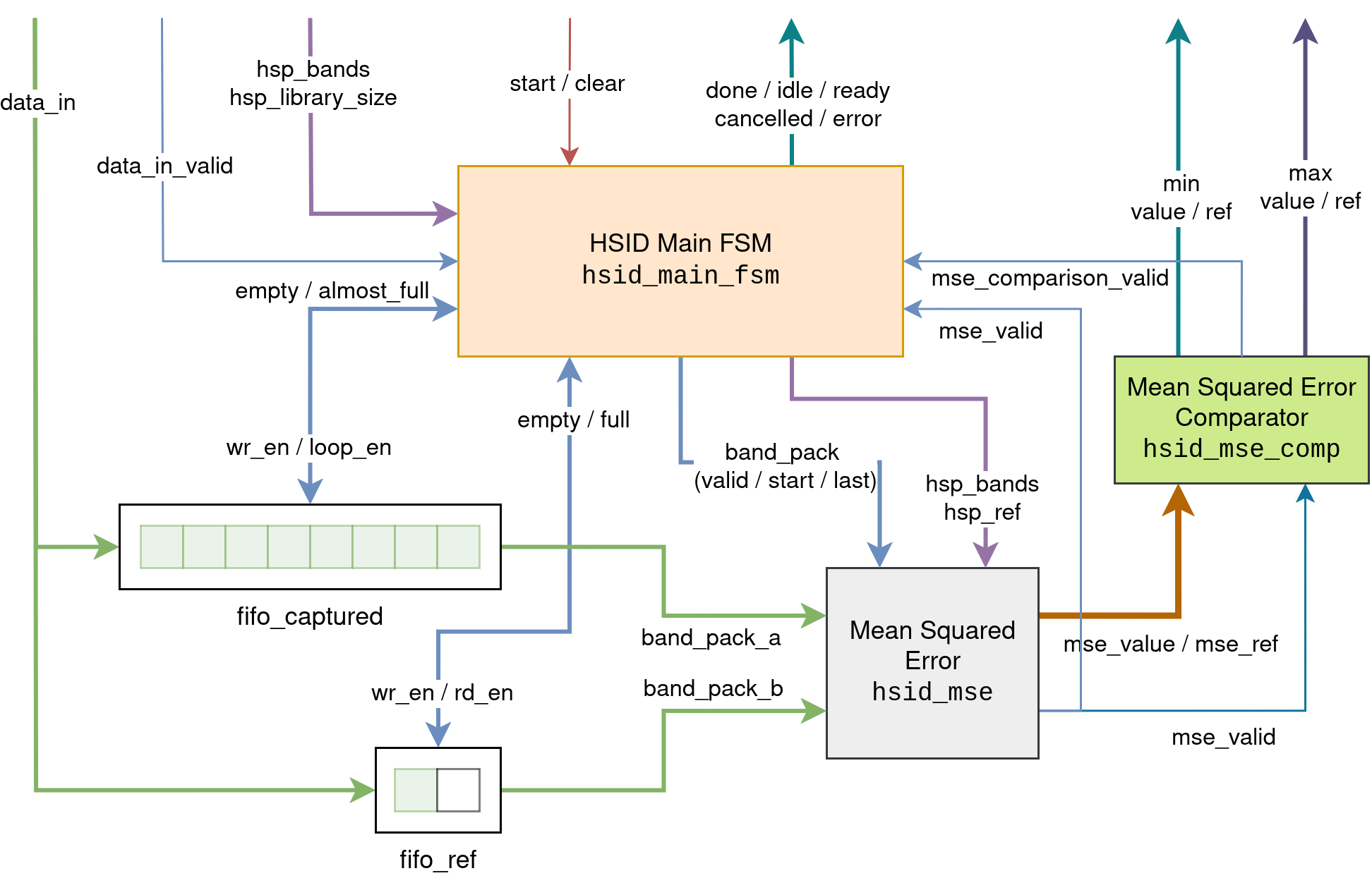
This module integrates the modules described previously and serves as the main IP core of the project. Using input data from the HSPs and reference signatures, it determines which reference signature most closely matches the captured HSP. The different modules are interconnected as shown in the figure below, in which signals are grouped semantically to avoid cluttering the diagram.
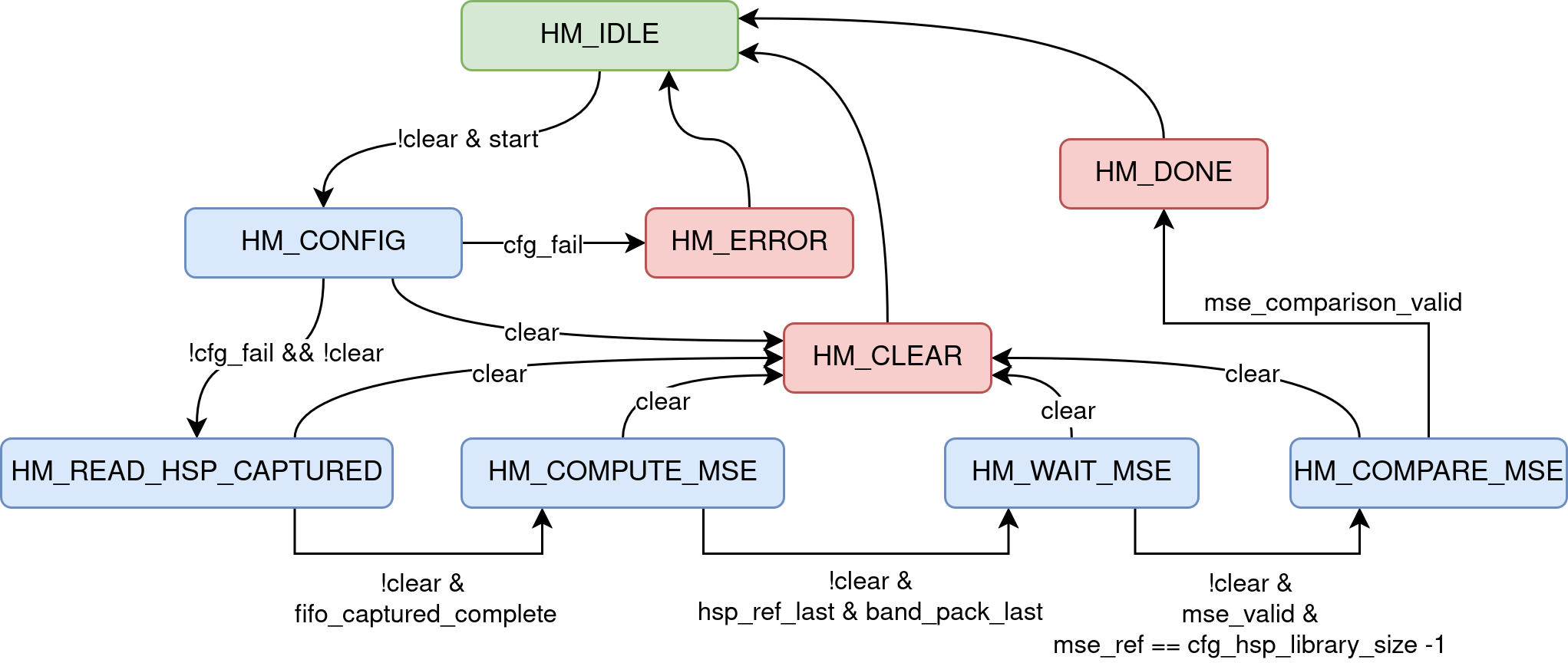
The synchronization of internal processes is managed by an FSM implemented
in the hsid_main_fsm module. The table and figure below summarizes the
function of each FSM state and its the corresponding FSM graph.
| State | Description |
|---|---|
HM_IDLE |
Idle state |
HM_CONFIG |
Register hsp_bands and hsp_library_size |
HM_READ_HSP_CAPTURED |
Write the captured HSP into the FIFO |
HM_COMPUTE_MSE |
Write the reference signature into the FIFO and compute the MSE |
HM_WAIT_MSE |
Wait until the last MSE computation is complete |
HM_COMPARE_MSE |
Wait until the last MSE comparison is complete |
HM_DONE |
Process complete |
HM_CLEAR |
Cancel the process |
HM_ERROR |
Configuration error |
The internal state of the module is exposed through the block control interface
(handshake) via the signals idle, ready, done, cancelled, and error.
The table below lists the values of these signals depending on the current FSM
state.
| State | idle |
ready |
done |
cancelled |
error |
|---|---|---|---|---|---|
HM_IDLE |
1 | 0 | 0 | 0 | 0 |
HM_CONFIG |
0 | 0 | 0 | 0 | 0 |
HM_READ_HSP_CAPTURED |
0 | 1 | 0 | 0 | 0 |
HM_COMPUTE_MSE |
0 | !fifo_ref_full |
0 | 0 | 0 |
HM_WAIT_MSE |
0 | 0 | 0 | 0 | 0 |
HM_COMPARE_MSE |
0 | 0 | 0 | 0 | 0 |
HM_DONE |
0 | 0 | 1 | 0 | 0 |
HM_CLEAR |
0 | 0 | 0 | 1 | 0 |
HM_ERROR |
0 | 0 | 0 | 0 | 1 |
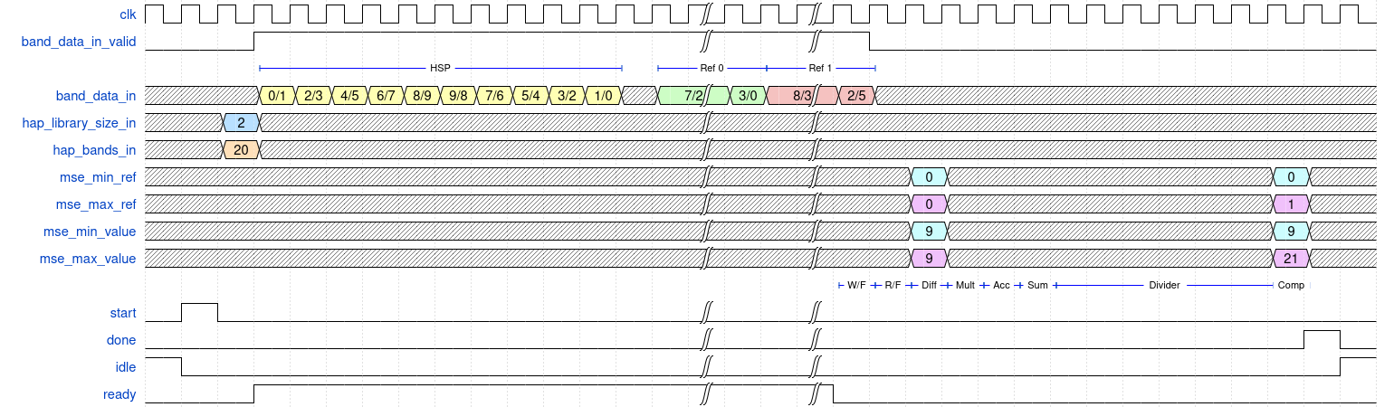
Assuming there are m reference signatures and each HSP contains n bands, the estimated latency in cycles for this module is given by:
The constant term 7 accounts for the final operations, which include: reading
from the FIFO, subtraction, multiplication, accumulation, accumulator
summation, comparison, and assertion of the done signal. The other \(K + 1\)
cycles depends on the dimension of the module hsid_divider. The figure below
shows an example waveform for an HSP with 10 bands and 2 reference
signatures using a 5-bit divider. There is also some description of the final
steps in the pipelines.